Case Study: A Unique Reverse Engineering Project Combining CMM and 3D Laser Scanning
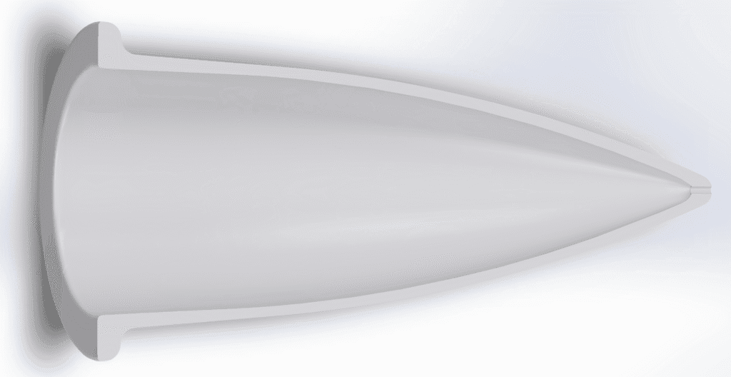
Our customer approached us, with an interesting engineering challenge that required a more comprehensive approach beyond the standard scanning and modelling process. They required an accurate solid model with as much details as possible for both the internal and external surfaces of their ceramic radome; all within a cost effective framework. We achieved this by combining our 3D scanning and CMM inspection capabilities together with our reverse engineering and CAD modelling skills.
High coverage laser scanning for external surfaces
Our Einscan HX laser scanner provided high accuracy data with extensive coverage of the radome’s external surfaces. The HX scanner has a volumetric accuracy of just 0.04+0.06mm/m and the point spacing can be set as small as 0.05 mm. However laser scanning requires stereo line of sight onto surfaces to triangulate points. Whilst the external shape of the radome was easily accessible for 3D scanning, the deep internal cavity was not.
High accuracy CMM scanning for internal surfaces and over-checking external surfaces
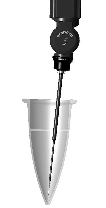
Given the scanning challenges posed by the deep cavity, we used our REVO CMM inspection capabilities to complement our Einscan HX laser scanner. The REVO CMM system gives extremely high accuracy data with a volumetric accuracy of 0.0023+0.003mm/m. Combined with its ability to scan cross sectional profiles in deep cavities, it is ideally suited to capturing the form of the internal features.
A hybrid approach to reverse engineering
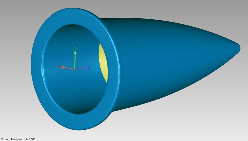
Exploiting the strengths of each scanning system, our solution was to use the laser scanner to generate an STL model for the all the external surfaces and as much of the internal surfaces as feasible. This partial model, shown in figure 1, was then used to create an initial CMM scanning program. We first verified the model integrity by over-checking external profiles with the CMM. Having established confidence in the model, we began scanning internal cross sections every 15 degrees using unknown path scanning.
With both the CMM scanning and Laser scanning completed, we were able to digitally assemble the two data sets within our CAD software and begin the final modelling. The laser scan data, with its high density of data points was first wrapped to form a CAD surface model. We then lofted a surface through the CMM cross sectional data. Finally we created a single Solid model by stitching the surfaces into a closed body. This then gave us the high quality solid CAD model required by our customer.