A ballooned drawing is an engineering drawing where each dimension, note, tolerance or specification has been assigned a unique reference number.
Ballooning an engineering drawing provides a structured way to reference drawing requirements by assigning a unique reference number to each characteristic. It is a key part of many inspection processes, especially First Article Inspection, and an essential step for inspecting complex parts with multi-page drawings.
The numbered balloons create a simple way to reference each drawing requirement throughout the part’s lifecycle. They provide a simple way to reference results in an inspection report back to the original requirement, making it easier to demonstrate that every requirement has been accounted for.
The process can also be referred to as bubbling, or numbering a drawing. These terms are used interchangeably across manufacturing and inspection and all describe the same approach of assigning a unique reference or characteristic number to each feature.

Why are drawings ballooned?
The primary purpose is traceability. A ballooned drawing provides a structured way to identify and track every requirement on a drawing, helping to ensure nothing is overlooked and that reports can be linked back to the original design specification.
Because each result is tied to a unique number, it is easy for a customer, auditor or member of the quality team to take any line in the final report and quickly locate the corresponding drawing requirement, along with the results in any supporting inspection records.
Where drawings are not ballooned, characteristics are typically referenced using structured identifiers such as feature type, nominal size and instance, for example Dia_42.161_A. While this approach can work, it relies on consistent naming conventions and is generally less intuitive to cross-reference than a clear numbering system.
What should be ballooned?
As a general rule, anything that is part of the product definition should be assigned a feature number. This ensures that characteristics can be traced through the inspection process and referenced consistently within inspection reports.
Common examples include:
- Linear & angular dimensions
- Diameters and radii
- Geometric tolerances (GD&T)
- Surface finish requirements
- Thread specifications
- Material specifications
- Coating & heat treatment requirements
- Drawing notes
Basic & Theoretically Exact Dimensions (TED)
Some characteristics require more consideration. Basic dimensions under ASME standards, and theoretically exact dimensions under ISO standards, do not normally have a direct inspection result associated with them. Instead, they define the location, orientation or profile requirements controlled by a geometric tolerance.
For this reason, some organisations choose not to balloon them. However, many inspectors still assign them balloon numbers because they form part of the definition of the requirement being inspected. Ballooning them also makes it easier to reference specific dimensions during discussions with customers, inspectors and manufacturing personnel.
For example, a hole with a true position tolerance of Ø0.10 to datums ABC would have the position tolerance ballooned, as this defines the acceptance criteria for inspection.
The basic dimensions that locate the hole (for example X and Y coordinates from the datums) may also be ballooned, even though they are not used to determine pass or fail. In practice, these values are often used by the machinist to set out the feature and by engineers when reviewing manufacturing variation.
Reference dimensions
Reference dimensions are another area where practices vary. Because reference dimensions are informational and do not define an acceptance criterion, they are not normally included within inspection reports. Some organisations still balloon them for completeness, while others exclude them entirely.
In practice, we would usually recommend ballooning basic dimensions. They contribute to the definition of a feature and ballooning them ensures a clear reference during inspection and when reviewing results. Reference dimensions are generally excluded, as they are informational and not subject to inspection.
How to create a ballooned drawing?
Ballooning can be done manually or using inspection software, depending on the drawing and available tools.
For simple or one-off inspections, this may involve marking up a PDF and transferring characteristics into an inspection report. This works for low characteristic counts, but becomes slower and more error-prone as complexity increases.
Ballooning is most commonly carried out using software such as SOLIDWORKS® Inspection, InspectionXpert, or similar tools. These systems can identify drawing characteristics, assign balloon numbers and generate a structured inspection report, often including AS9102 Form 3 layouts.
Although this reduces manual work, the output still needs checking to ensure notes, GD&T and non-standard callouts have been captured correctly.
Model-based definition (MBD) takes this a step further by embedding product and manufacturing information (PMI) directly within the 3D CAD model. In these workflows, characteristic identifiers are associated with the PMI rather than a separate 2D ballooned drawing, allowing inspection requirements to be derived directly from the model while maintaining traceability for reporting.
Numbering and layout conventions
There is no single universal standard for how balloon numbers must be applied, but there are common conventions used across most inspection drawings.
Balloon numbers are typically applied in a logical sequence to make the drawing easier to read. The most common approaches are:
- Top-left to bottom-right across each sheet
- Clockwise around the sheet
On larger drawings, one of the above methods may be applied per view, rather than across each sheet. Ultimately, the method used is usually less important than consistency. The goal is that the numbering can be followed easily when cross-referencing the inspection report.
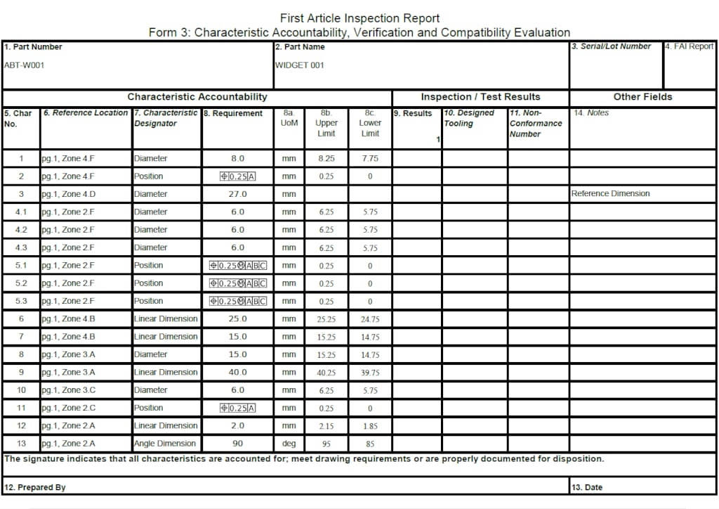
Where a feature appears multiple times, there are two common approaches. In many cases, a single balloon number is assigned to the requirement, with sub-identifiers used for each instance, for example 5.1, 5.2, 5.3. This keeps the instances grouped under one requirement while still capturing a result for each.
Alternatively, each instance may be assigned its own sequential balloon number (5, 6, 7), particularly where features are treated as independent characteristics.
The choice between these approaches depends on customer requirements and how the inspection results need to be reported.
On larger or multi-sheet drawings, location references are sometimes used to assist navigation, but these are typically recorded in the inspection report alongside the balloon number rather than on the drawing itself.
Ballooned drawings in FAI and PPAP
Ballooned drawings are most commonly used as the basis for First Article Inspection (FAI) reports. Each balloon number on the drawing is used to identify a specific characteristic, which is then carried through into the inspection report against its measured result.
In aerospace applications, these balloon numbers align directly with AS9102 Form 3 (Characteristic Accountability, Verification and Compatibility Evaluation). Form 3 is where each characteristic is listed, measured results are recorded, and any non-conformance is identified. The balloon number provides the link between the drawing and each line on the form, ensuring every requirement can be traced back to its origin.
In automotive PPAP submissions, the same principle is applied, using numbered drawings to structure dimensional results and maintain traceability between requirements and inspection data.
The key requirement is consistent referencing between drawing, characteristic and recorded result.
Need a drawing numbering up?
If you need a part inspecting with a ballooned drawing, our First Article Inspection service covers ballooning, inspection, and Form 3 reporting.