Reverse Engineering Services
We are a UK-based reverse engineering services provider with 30+ years of experience, trusted by aerospace and automotive suppliers. We convert physical parts into production ready 3D CAD models giving you reliable data for manufacture, modification, and product development.
ISO 9001:2015 Certified • 0.003 mm Measurement Accuracy • 30+ Years Experience
See the Transformation
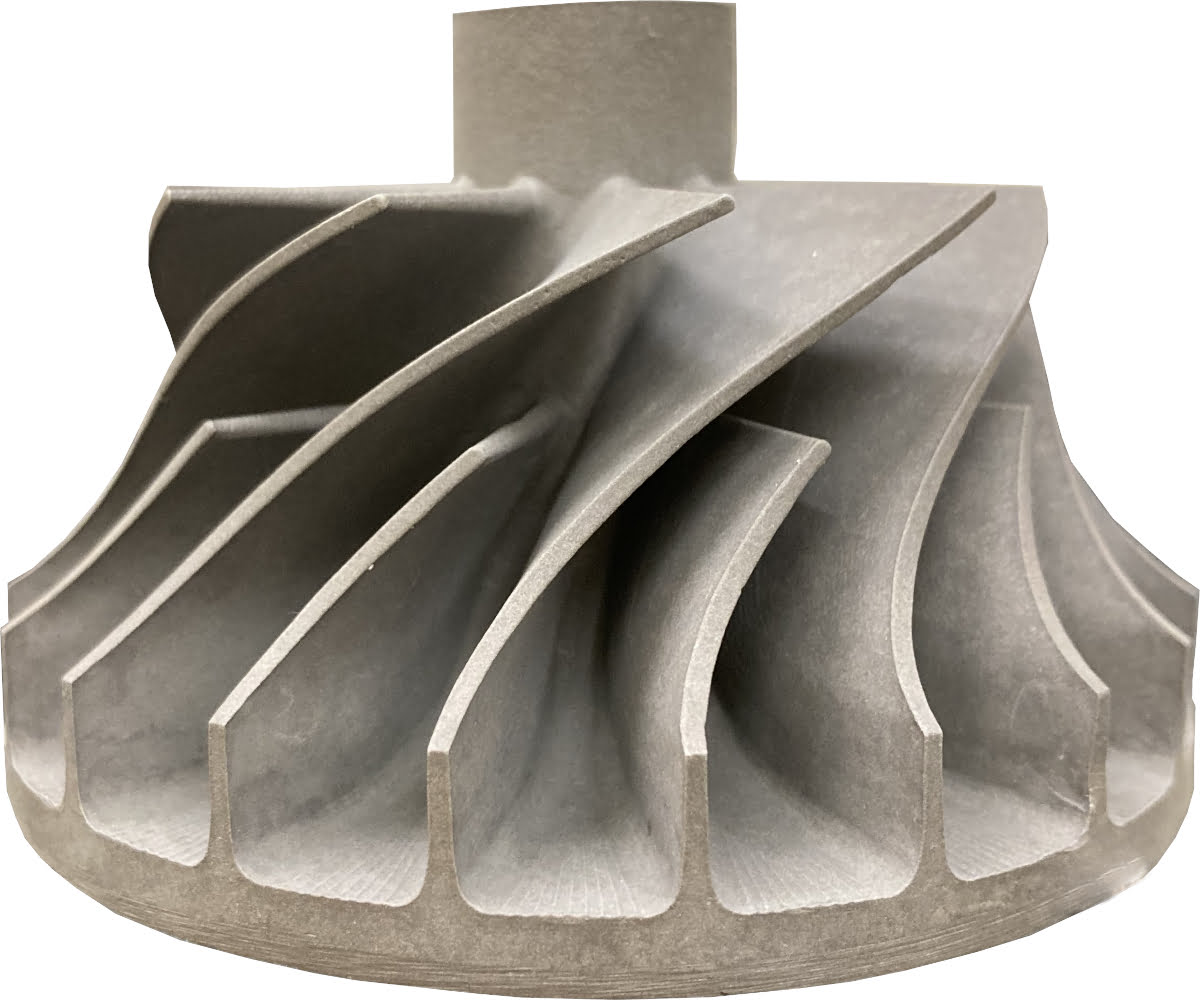
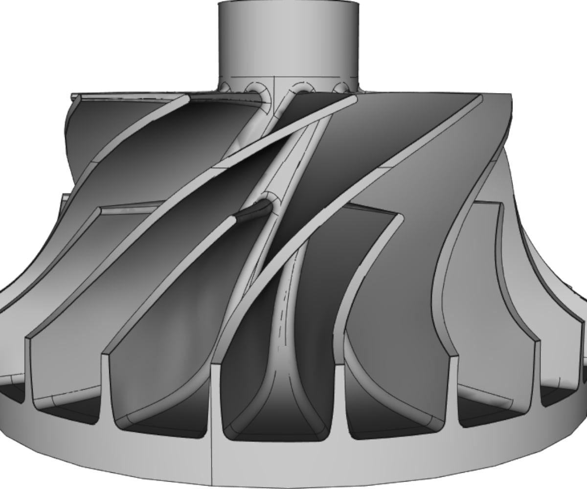
Physical part to production-ready parametric CAD model. Slide to compare.
Our Reverse Engineering Process
We take your part, measure it, and turn it into a 3D model you can use for 3D printing, manufacturing, or further design work.
Step 1
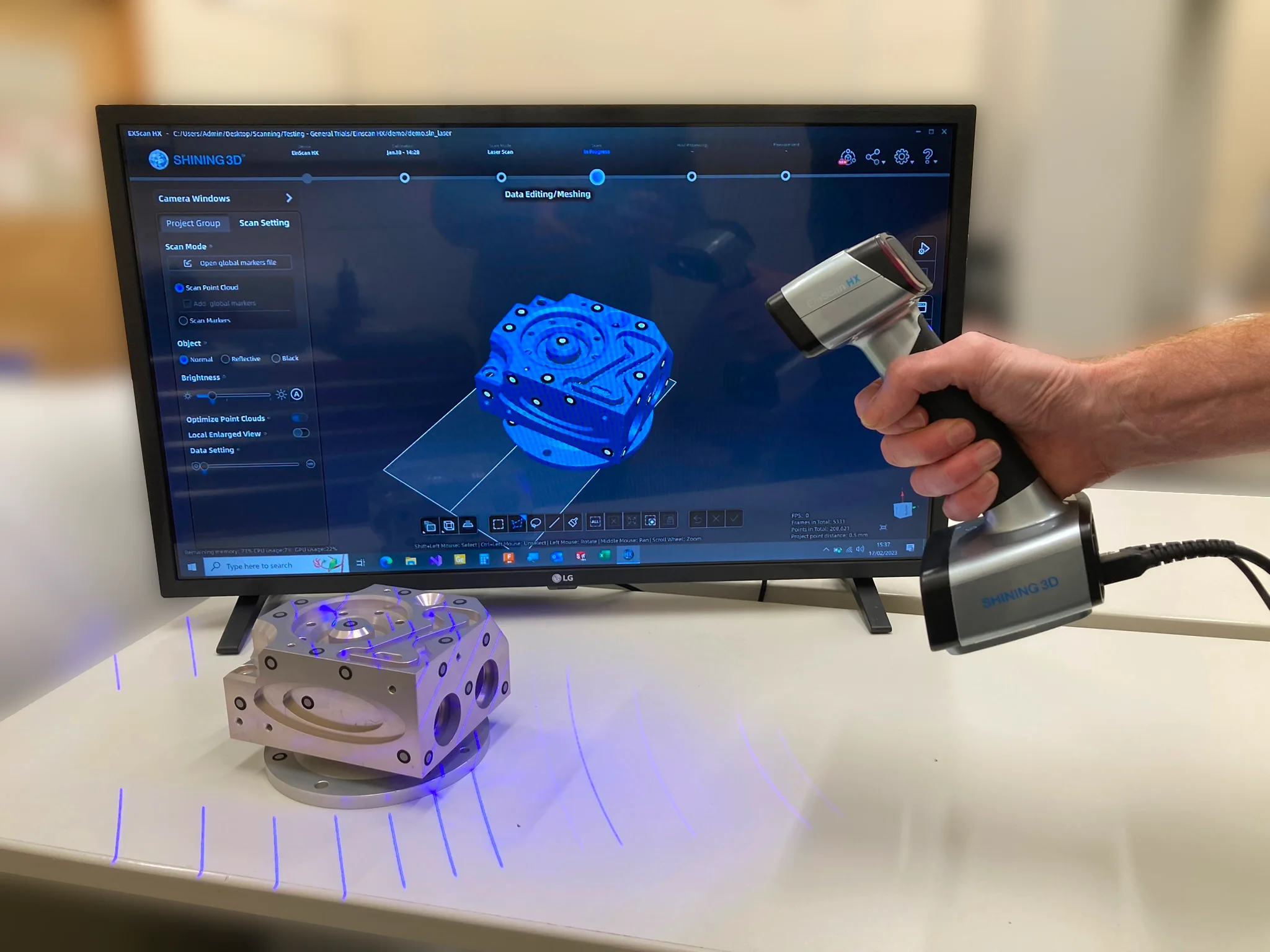
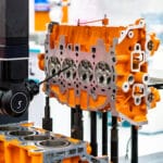
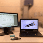
Data Capture
Our engineers assess your component’s geometry and required accuracy to determine the most suitable approach. They will use a combination of 3D Scanning, CMM Inspection, and hand tool measurements to complete the project efficiently.
Step 2
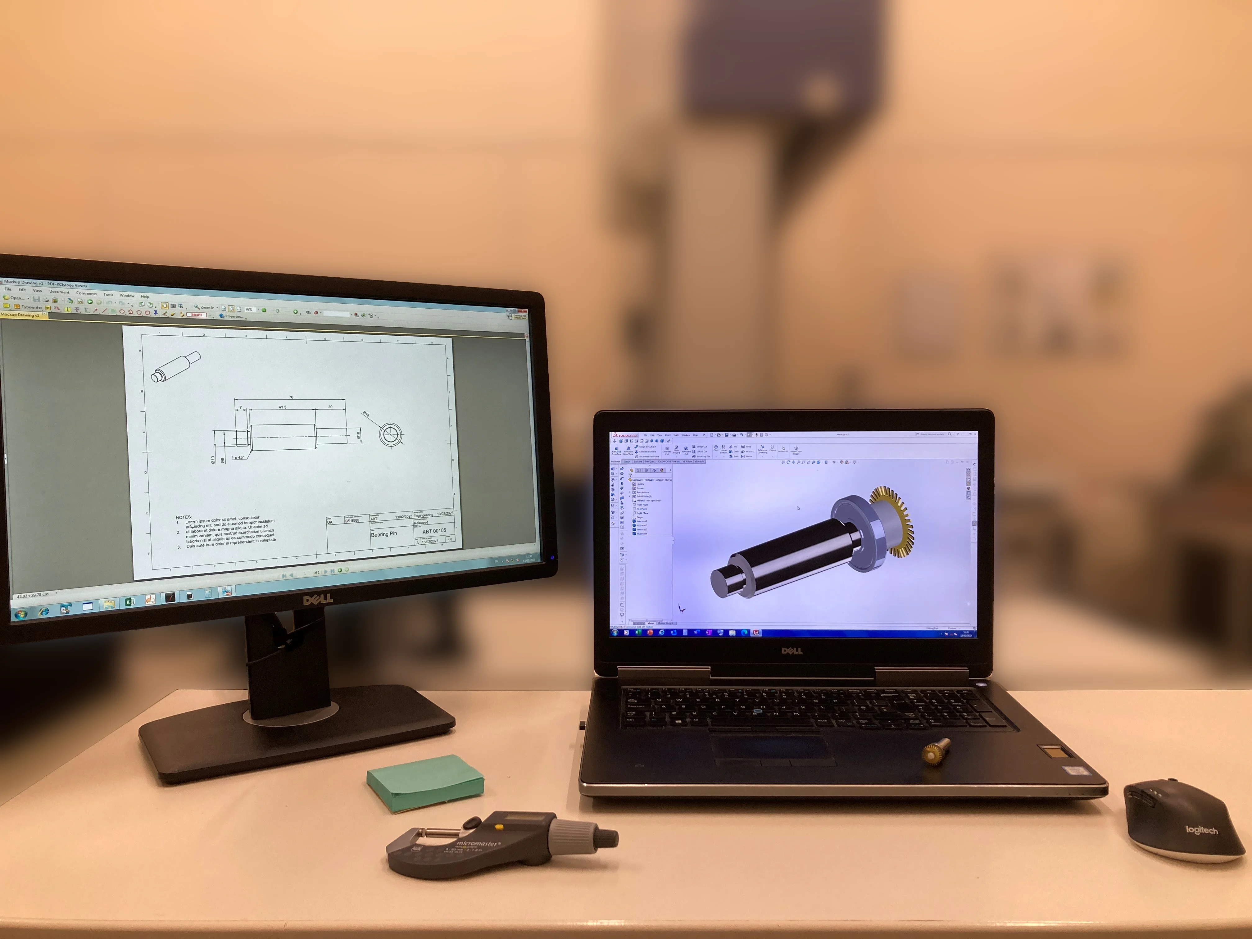
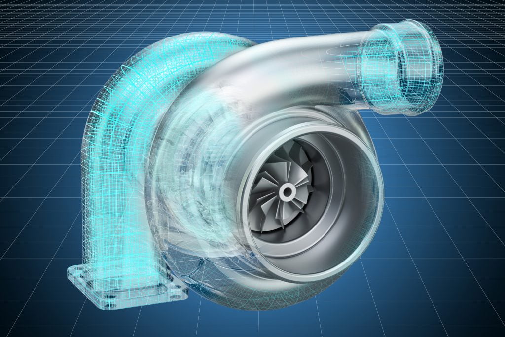
CAD Modelling
Our engineer will reverse engineer a parametric CAD model based on all the measurement data to create a design intent model. Alternatively, we can use NURBS surfaces to create a model that represents your part’s exact geometry, including any imperfections.
Step 3
Delivery
We deliver your CAD model in your chosen format:
- Neutral formats (STEP, IGES, STL)
- Native CAD formats (SolidWorks, AutoCAD, Autodesk Fusion, Parasolid)
You own the model to use however you wish.
Want to understand the technical process in detail? Read how reverse engineering works.
Uses For Our Reverse Engineering Services
Every project is different, but the goal is the same: turning your physical parts into usable CAD models. Here are some of the most common reasons our customers come to us.
Manufacturing Legacy Parts
Many older parts pre-date modern manufacturing and were never designed in CAD. We can create new models for your parts, ensuring any undocumented design changes are included in the final design.
Replace Discontinued Parts
If the original manufacturer no longer exists, we can reverse engineer the obsolete part so you can source replacements, protecting your business continuity.
Repair Broken Machinery
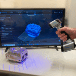
Need to repair a worn or broken component from your machine tool? We can come to your site with our portable 3D scanner to capture your part, then produce an accurate CAD model for you to re-manufacture a replacement.
Document Current Designs
Does your design match reality? We can document what your production process is actually making. This enables you to digitally analyse your parts (FEA/stress analysis) as well as giving you updated models for manufacture.
Competitor Analysis
Need a digital representation of your competitor’s parts? We can help. Whether you suspect them of infringing on your patent or want to understand their methods, we can create detailed models for analysis.
Design Compatibility
If you need to ensure your design can interface with third-party components but cannot obtain CAD models for them, we can create detailed placeholder models so your design fits and works with these parts.
Frequently Asked Questions
How long does a reverse engineering job usually take?
Typically jobs take around 1 week, depending on the complexity. If you have a specific deadline, let us know and we’ll do our best to help.
Do you offer on-site scanning or do parts need to be sent in?
We offer both: we can scan your part on-site for large/installed items or you can send the part to our facility for scanning and inspection.
What file format will I receive my model in?
We can provide models in most neutral CAD formats including STEP and IGES. We can also supply models in various native formats including Solidworks (.sldprt), AutoCAD (DWG), Fusion (.f3d), Parasolid (x_t), etc. See our downloads page for example files.
Can you provide 2D drawings as well?
Yes, we can provide 2D drawings for models produced using our reverse engineering service.
How accurate are your models?
The measurement stage is the foundation for creating accurate models. We use high-accuracy CMMs (from 3 µm) and 3D scanners (from 35 µm) to capture the data.
Can you reverse engineer assemblies?
Yes, as long as we can disassemble it enough to see all the features that require modelling.
Can you reverse engineer damaged or worn components?
Typically yes. To get a definitive answer, send us some photos of your damaged or worn part and we’ll assess the feasibility.
Let’s make you a CAD model that works
Whether you need to manufacture a legacy component or analyse your design, our reverse engineering service can provide. We scan, we model, we verify. You get a CAD model you can actually use.
Projects We’ve Delivered
Discover how we’ve helped UK companies solve complex reverse engineering challenges
Reverse Engineering • Design Compatibility • Parametric Modelling
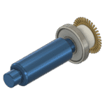
Reverse Engineering For Product Design
A specialist bicycle manufacturer needed CAD models for bought-out components to integrate into their designs. We reverse engineered their bicycle hanger using high-resolution 3D scanning and parametric modelling.
✓
Challenge: No CAD data for bought-out components
✓
Solution: Scan + Reverse engineer using Autodesk Fusion
✓
Deliverable: A cost effective placeholder CAD model


Reverse Engineering • Automotive • SOLIDWORKS
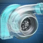
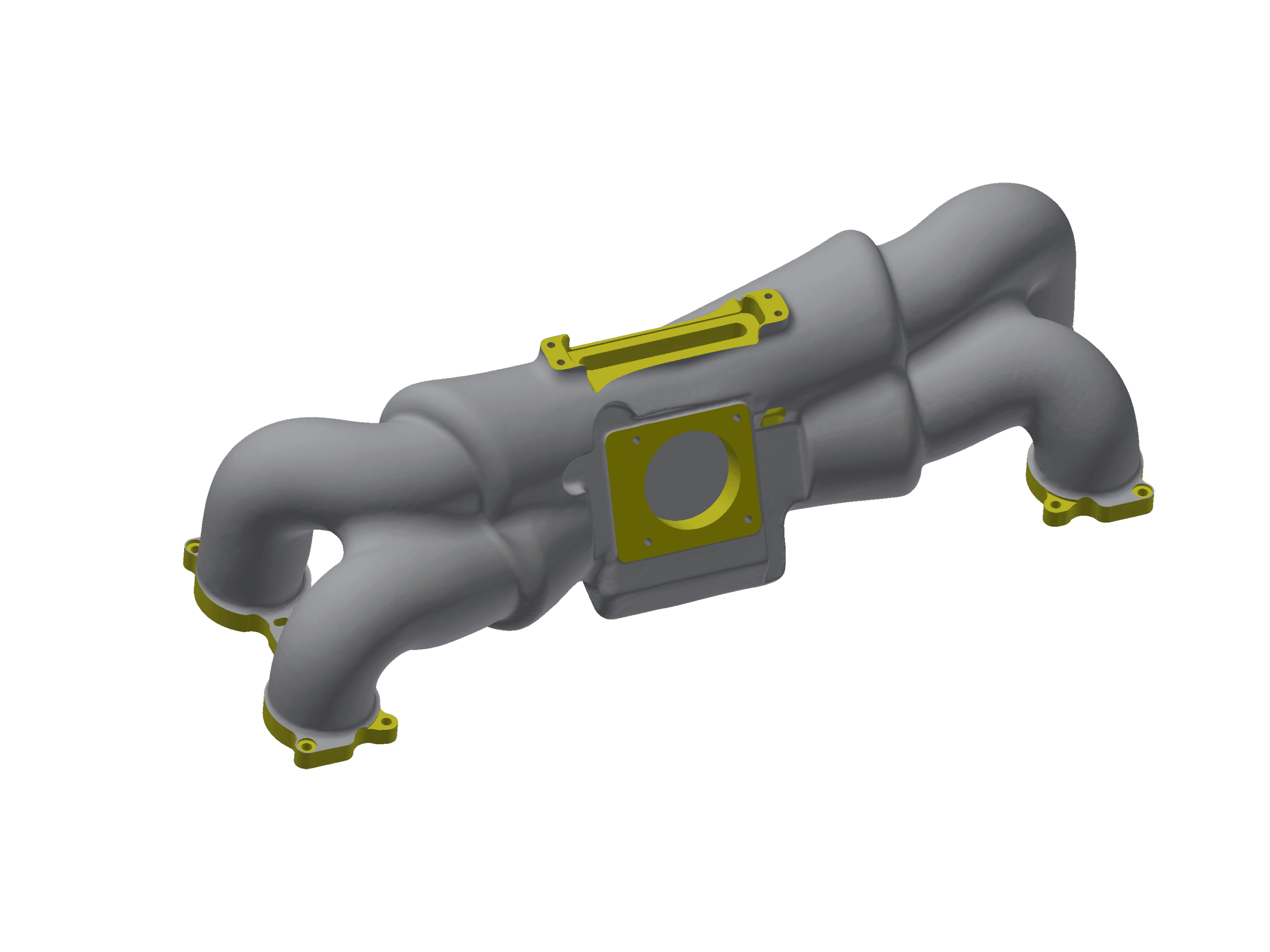
Custom Manifold from Cosworth Casting
Combined 3D laser scanning with CMM inspection to transform a Cosworth casting into a custom Subaru Impreza inlet manifold, complete with production-ready engineering drawings.
✓
Challenge: No original CAD data for either component
✓
Solution: 3D scanning + CMM verification + CAD modelling
✓
Result: Production-ready 2D drawings with machining specs
Trusted by Manufacturing Professionals
Don’t just take our word for it. Our customers consistently rate us 5 stars for precision, turnaround times, and technical expertise.
Customer feedback:
“Outstanding work. Very quick turn around, accurate and faultless.”
Roger Osborne
Ready to Start Your Project?
Contact us today for a no-obligation quote. We’ll assess your requirements and recommend the best approach for your component.
ISO 9001:2015 Certified • 30+ Years Experience • UK-Based Engineering Team